> DDS Function Signal Generator
> Digital Multimeters
> Distortion Analyzer
> Four Probe experiment
> Function Generator
> IC Testers
> LCR Meters
> Oscilloscopes
> Power Supplies
> Pulse Wave Frequency Meter
> Signal / Function Generator
> Storage Oscilloscopes
> Two Probe Setup
> Withstand Tester
> General Physics Equipments
 
- Digital Micro Volt Meter
- Digital Nano Ammeter
- Digital Pico Ammeter
- Digital Gaussmeter
- Magnetic Field Measurement Apparatus
- Study of Dieletric Constant & Curie Temp of Ferroelectric Ceramics
- e/m Experiment
- Planck’s Constant by Photoelectric Effect
- Determination of Planck’s Constant by means of LED’s
- Frank Hertz Experiment
- Ionisation Potential Set-up
- Measurement of Magnetoresistance of Semiconductors
- Two Probe Method for Resistivity Measurement of Insulators
- Electron Spin Resonance Spectrometer
- Study of Thermoluminescence of F-centres in Alkali Halide Crystals
- Hall Effect in Metals
- Dependence of Hall Coefficient on Temperature
- Apparatus for the Measurement of Susceptibility of Paramagnetic Solution by Quinck's Tube Method
- Apparatus for the Measurement of Susceptibility of Solids by Gouy’s Method
- Magnetic Hysteresis Loop Tracer
   
> TEKON INSTRUMENTS
  - T100 Network Cable Detector
  - T550 Power Quality Analyzer
  - T560 Power Quality Analyzer
  - T600 Txr Turn to Ration
  - T610 Txr Analyzer
  - T650 ESS Diagnostic
  - T700 Ind. Robot Diagnostic
  - T800 EV-HEV Diagonstic


General Physics Equipments
Measurement of Magnetoresistance of Semiconductors -MRX-01
   

Introduction 

It is noticed that the resistance of the sample changes when the magnetic field is turned on. The phenomenon, called magnetoresistance, is due to the fact that the drift velocity of all carriers is not same. With the magnetic field on; the Hall voltage V is given as:

V = Eyt = |v x H|

which compensates exactly the Lorentz force for carriers with the average velocity; slower carriers will be over compensated and faster one undercompensated, resulting in trajectories that are not along the applied field. This results in an effective decrease of the mean free path and hence an increase in resistivity.

Here the above referred symbols are defines as: v = drift velocity; E = applied electric field; t = thickness of the crystal; H = Magnetic field


Description of the experimental setup
The set-up consists of the following:
  • Four probe arrangement
  • Sample: (Ge: p-type)
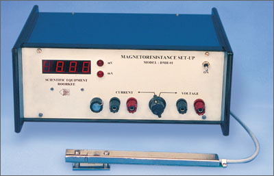
  • Magnetoresistance set-up, Model: DMR-11
  • Electromagnet, Model : EMU-50V
  • Constant Current Power Supply, Model : DPS-50
  • Digital Gaussmeter, Model DGM-102


Four Probe arrangement
It consists of 4 collinear, equally spaced (2mm) and individually spring loaded probes mounted on a PCB strip. Two outer probes for supplying the constant current to the sample and two inner probes for measuring the voltage developed across these probes. This eliminate the error due to contact resistance which is particularly serious in semiconductors. A platform is also provided for placing the sample and mounting the Four Probes on it.

Sample
Ge Crystal (n-type) dimensions : 10 x 10 x 0.5 mm.

Magnetoresistance Set-up, Model DMR-11
This unit consists of a digital millivoltmeter and constant current power supply. The voltage and probe current can be read on the same digital panel meter through a selector switch.


(a) Digital Millivoltmeter

Intersil 3½ digit single chip ICL 7107 been used. Since the use of internal reference causes the degradation in performance internal heating an external reference been used. Digital voltmeter is much convenient to use, because the input voltage of either polarity can be measured.

Specifications

Range : 0-200mV (100mV minimum)
Accuracy : ±0.1% of reading ± 1 digit


(b) Constant Current Power Supply

This power supply, specially designed for Hall Probe, provides 100% protection against crystal burn-out due to excessive current. The supply is a highly regulated and practically ripple free dc source.

Specifications

Current : 0-20mA Resolution : 10mA
Accuracy : ±0.2% of the reading ±1 digit
Load regulated : 0.03% for 0 to full load
Line regulation : 0.05% for 10% variation


* Products not listed can be ordered as per request.
* Model number may subject to change without intimation